
UPDATES//
11 December, 2025
CLAVICLE FRACTURE, WORK PAUSED
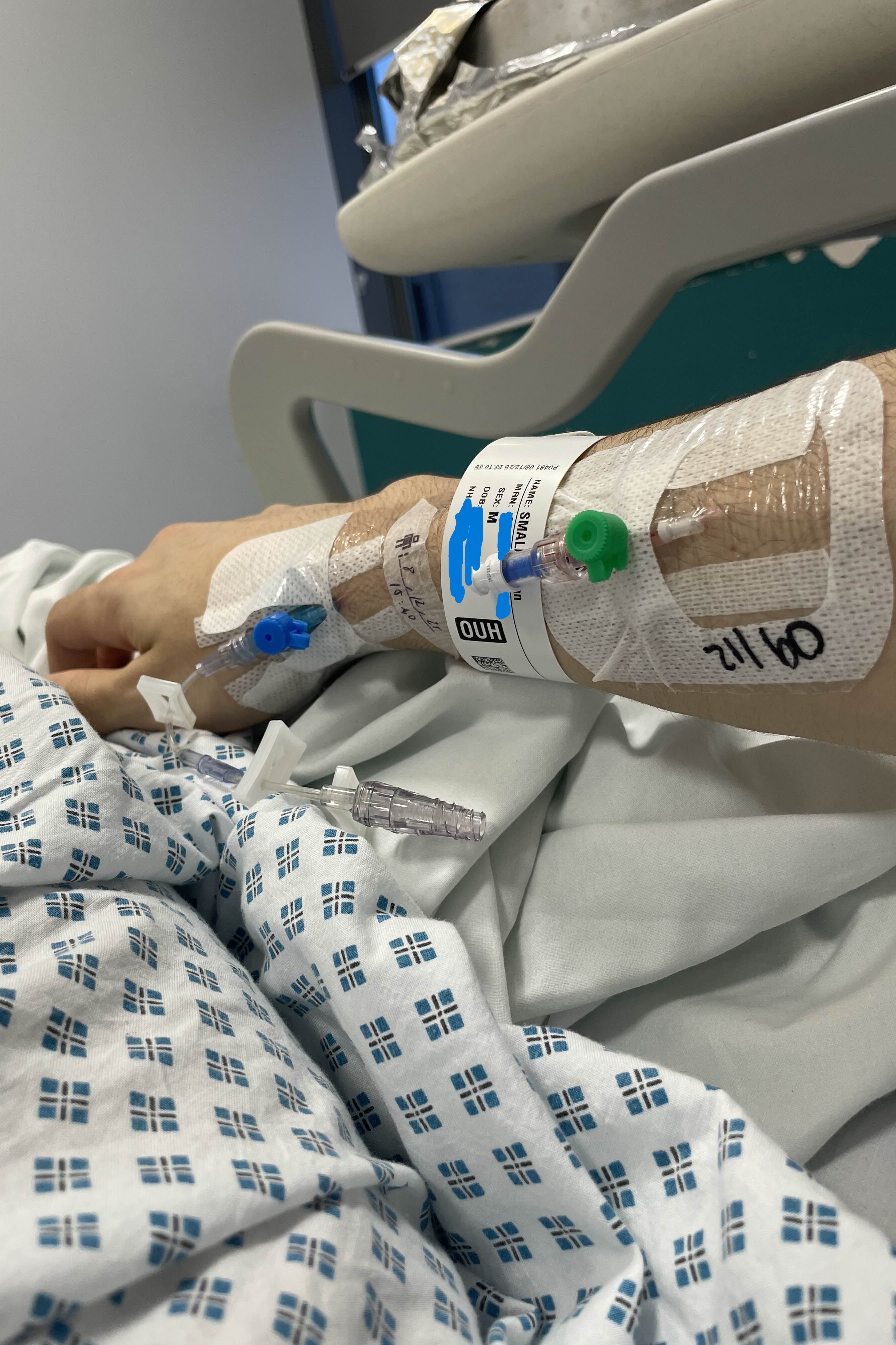
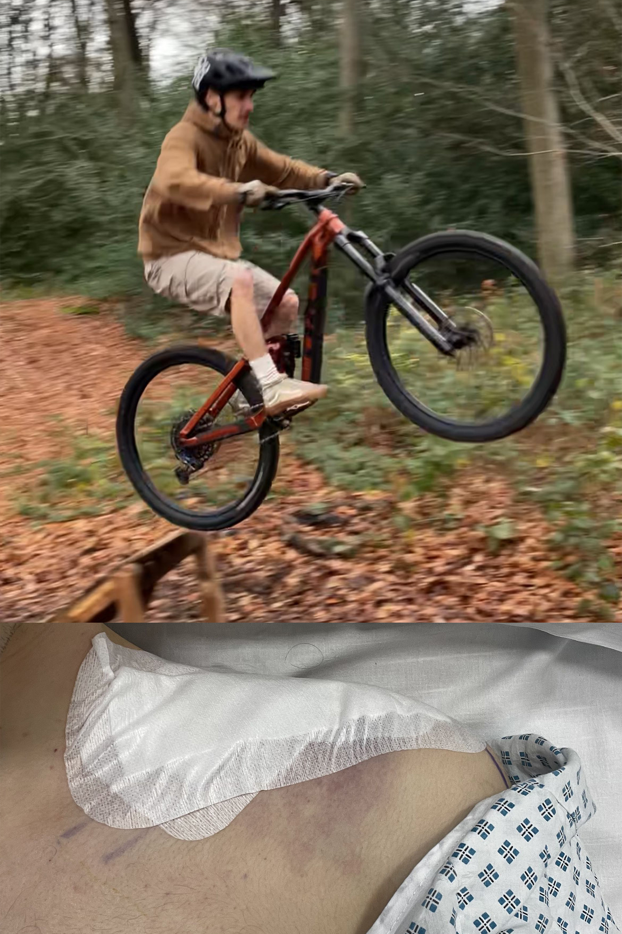
Codeine is amazing for pain numbing, but not great for having a clear mind for work. Whenever I'm feeling productive, I'll be taking time here and there to continue R&D for my acoustic capability, but hardware work is paused for now (pretty obvious as to why).
5 December, 2025
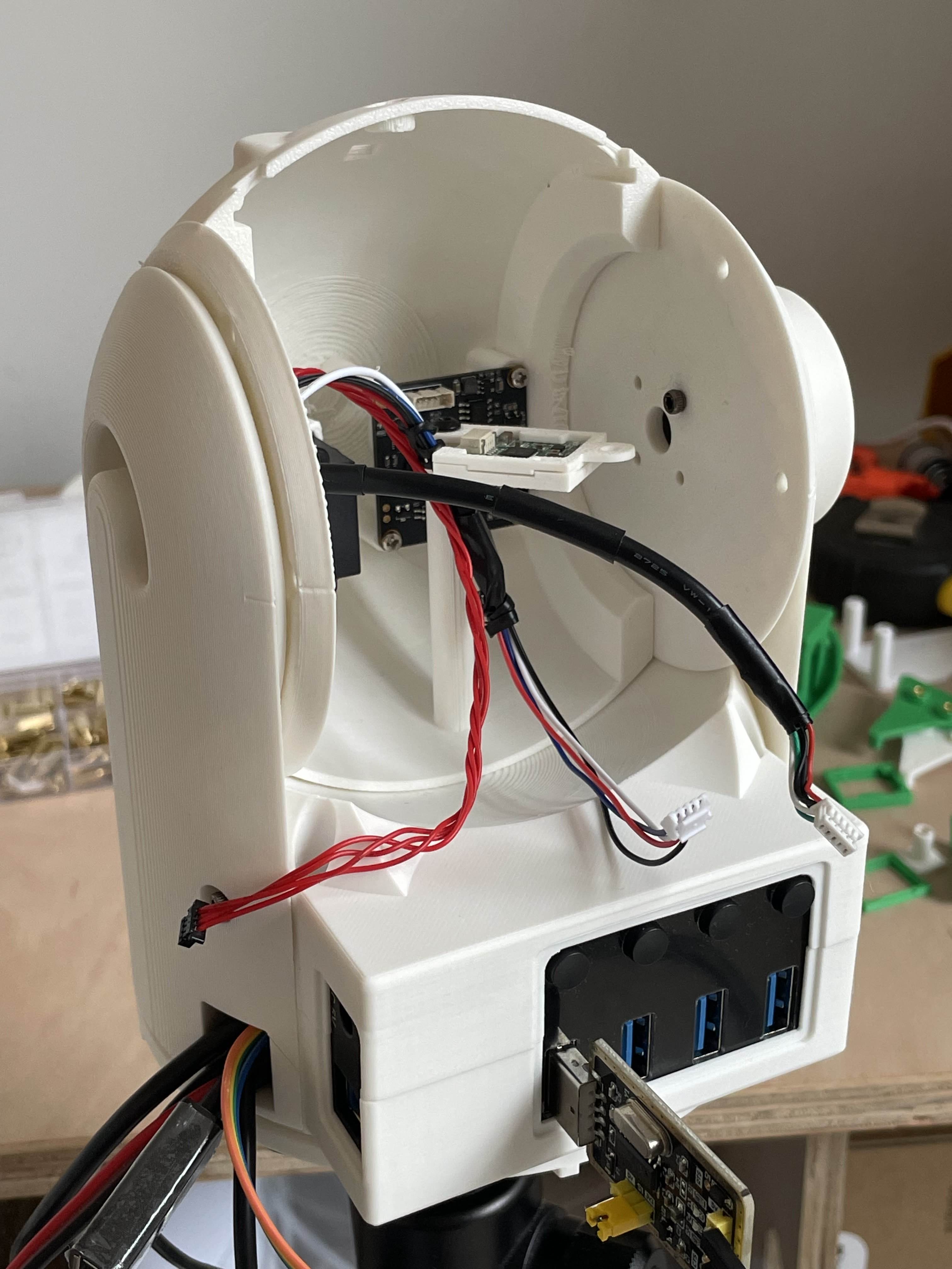
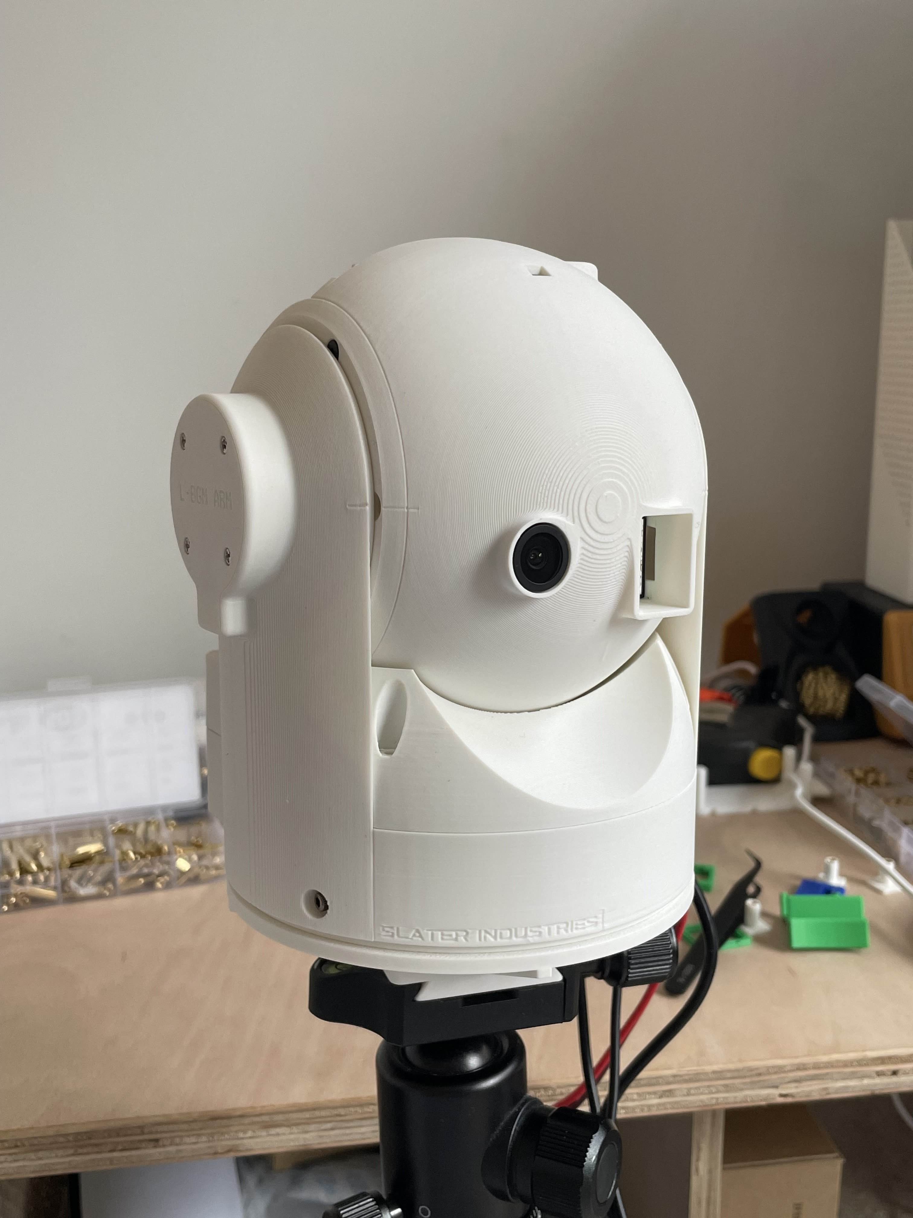
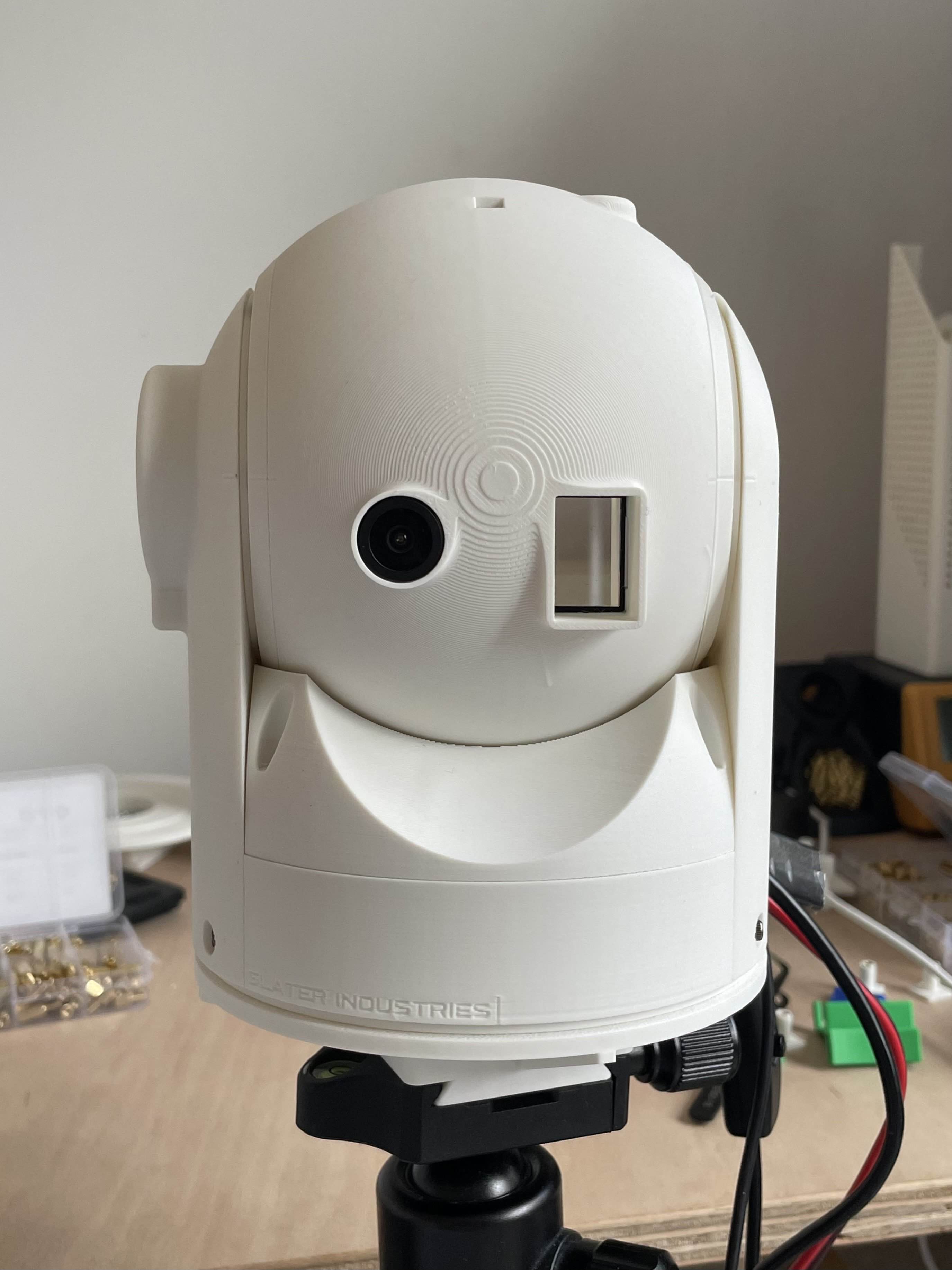
CAPSTONE v2
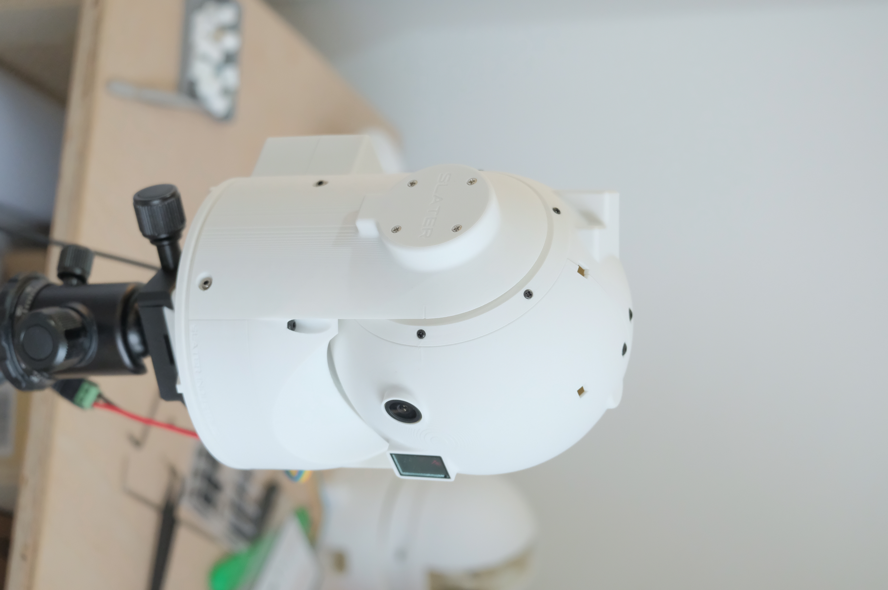
Capstone v2: I have made significant progress on the CAD design of Capstone v2, addressing the issues identified during the assembly of the first build. The new design includes improved cable routing, better access to internal components incl. wiring ducts, and better mounting solutions for the sensors (IMU, LRF). I have completed the printing of all the new parts, and I have assembled Capstone v2 (far easier than v1). The new design is identical to the first, but with some notable improvements:
- BGM Arm cable route covers are now detachable
- BGM Arm cable route support removal was easier
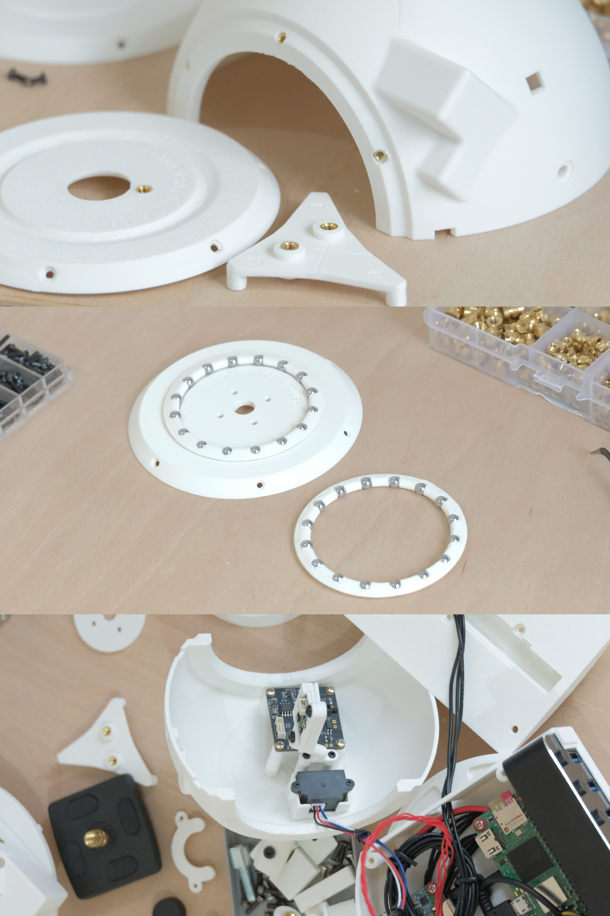
- X-Axis (vert) ball bearing interfaces utilise a new cage design with 16 BBs
- X-Axis (vert) ball bearing cages allow for pre-assembly, thus easier assembly of BGM arms and payload covers
- New ball bearing cage design provides much higher horiz. compressive force tolerance - less friction, secure fasteners
- 3mm clearance between payload sphere (convex) and base top sphere (concave) - frictionless movement
- M3 and M2 threaded inserts utilised on all hole interfaces - easier disassembly for internal adjustments
- Improved accessibility to payload inner comps and interfaces (IMU, L-side cover to BGM holes) thanks to new payload cover design
- New payload cover design overlaps payload body and allows for fastener access post assembly - unlike before
- New IMU arm mount interfaces with previous socket design and allows for assembly on 1 half of payload only
- New cover for L-BGM's X-axis rotation guide screw provides a more sealed enclosure
Updates on acoustic capability development and T-AUGS (aligned) in two weeks.
21 November, 2025
T-AUGS + ACOUSTIC ALGORITHM DEV
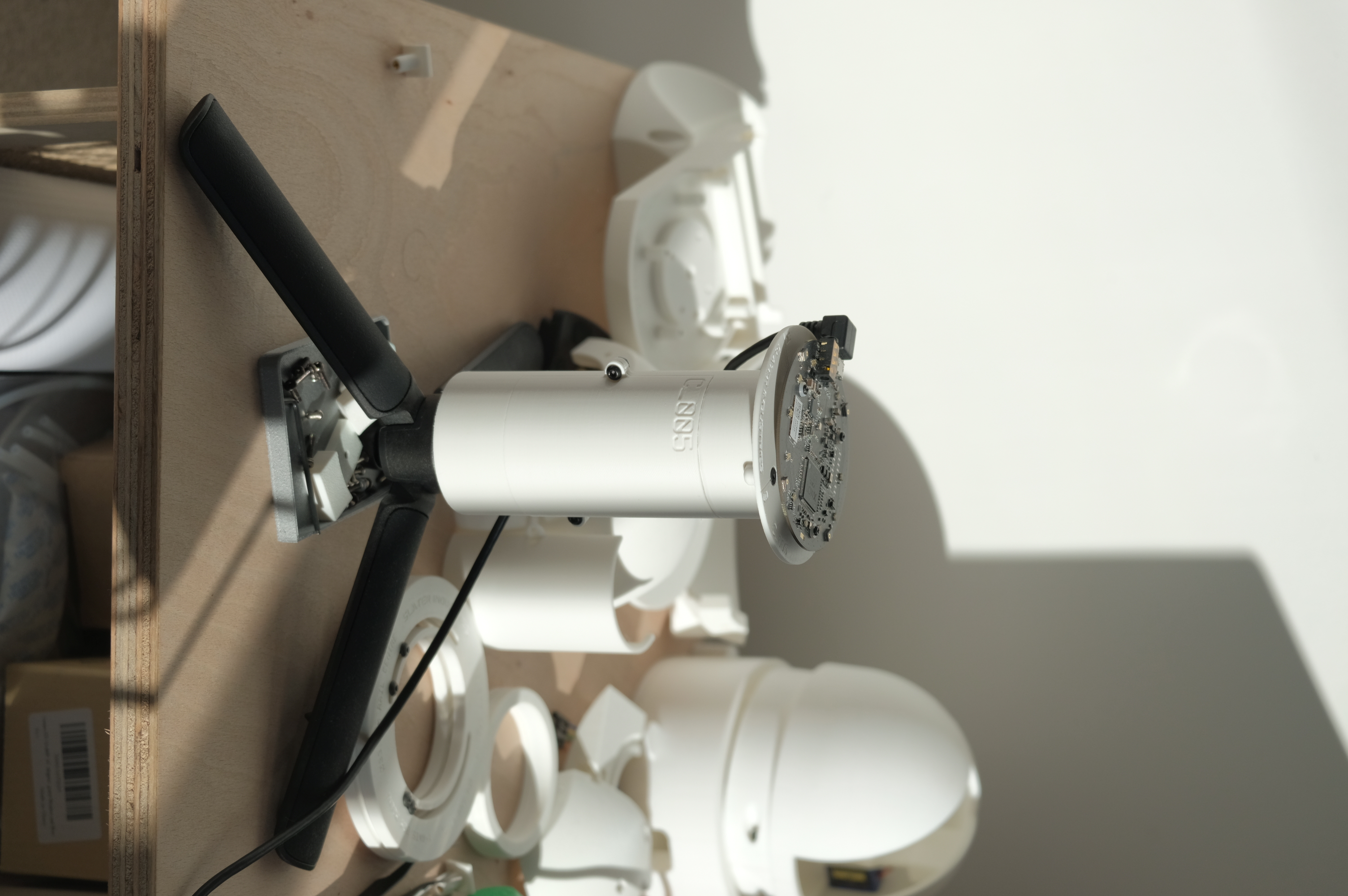
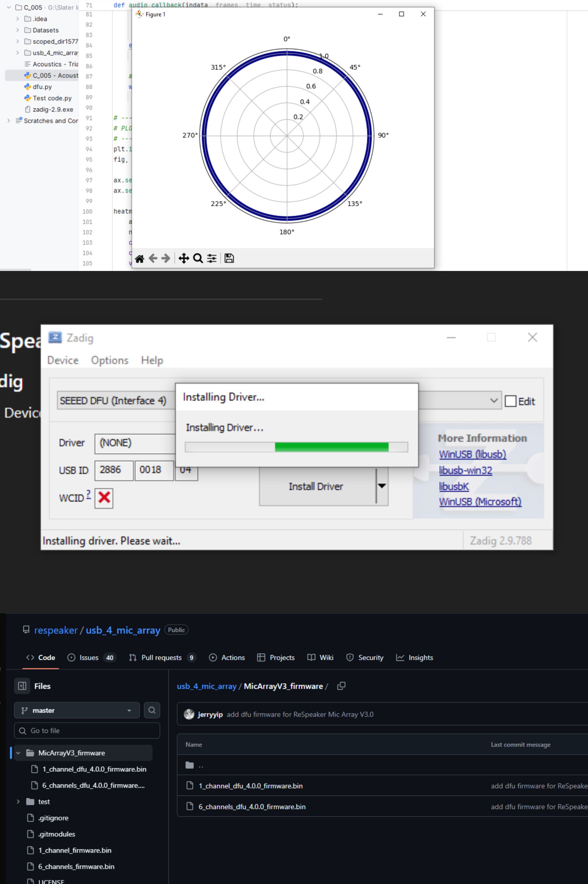
I'm busy tackling some driver challenges with the mic array. Currently, I’m working through the firmware and driver setup for the mic array, which has proven more challenging than expected. Windows has been giving me trouble during the DFU flashing process, with USB communication errors that suggest driver or connection issues. I guess it’s a reminder that even the most straightforward bought-in hardware steps can require careful attention to detail. Once this hurdle is cleared, I’ll be able to move forward with testing the audio capture and DOA algorithms, which is where the project really starts to come to life.
I read through some insightful documentation from Surrey Uni on DDL (Drone Detection and Localisation) systems, which has given me some good ideas on how to improve my algorithm further. I plan on implementing a more advanced TDOA (Time Difference of Arrival) algorithm next, which should improve the accuracy of the localisation. Additionally, I'll be exploring ML techniques to classify drone sounds from other ambient noises, which would enhance the detection capabilities of the system. This T-AUGS concept is also a platform which could be used to bootstrap Slater Industries provided I get it developed, tested, and sold into demanding markets such as Ukraine's critical infrastructure or high-risk facilities in need of very low-cost and basic UAS detection systems - This is something I will be looking into. Overall, I'm pleased with the progress made so far, and I'm excited to continue refining the acoustic detection system in the coming weeks.
7 November, 2025
BUILDING CAPSTONE
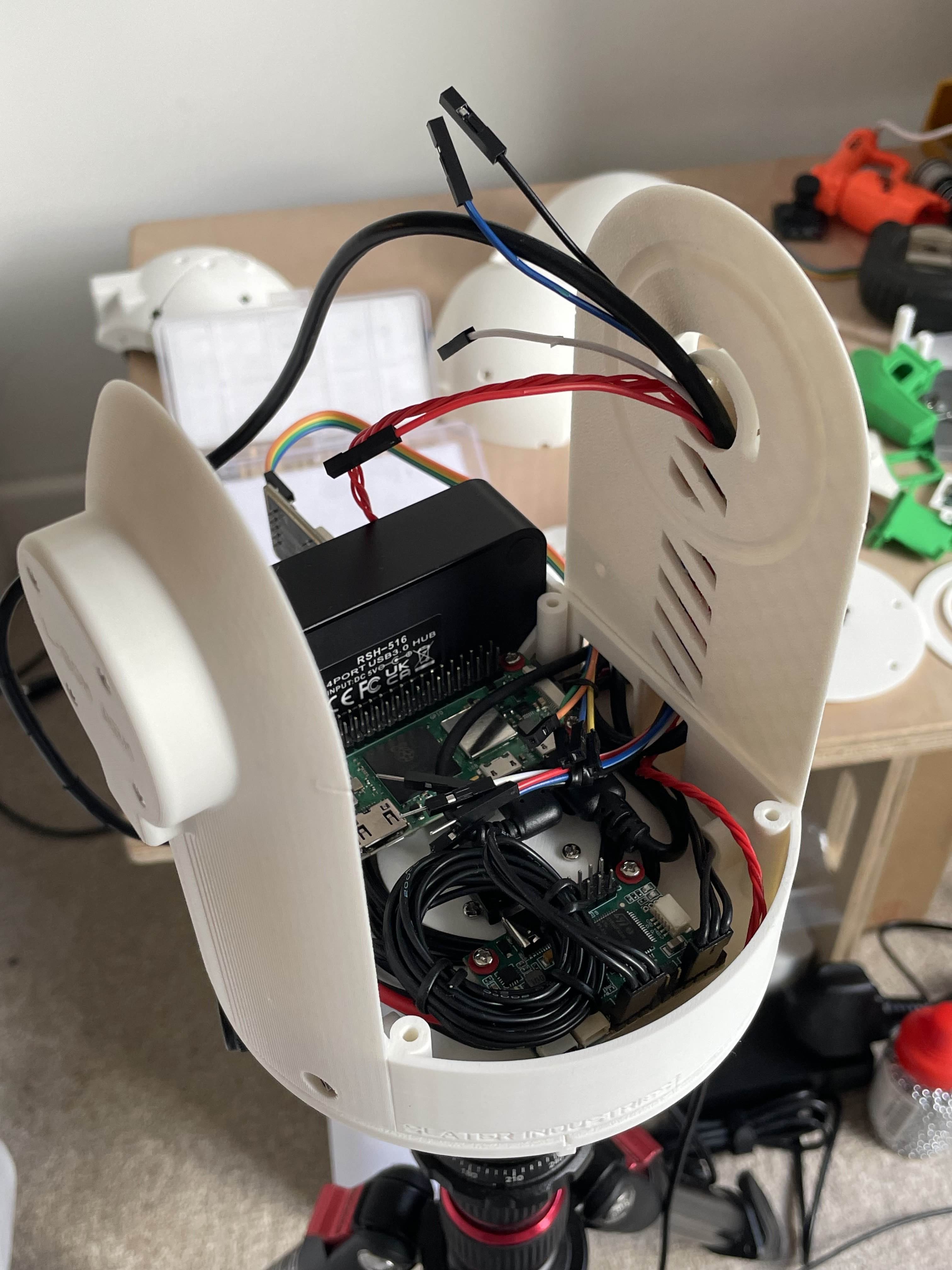
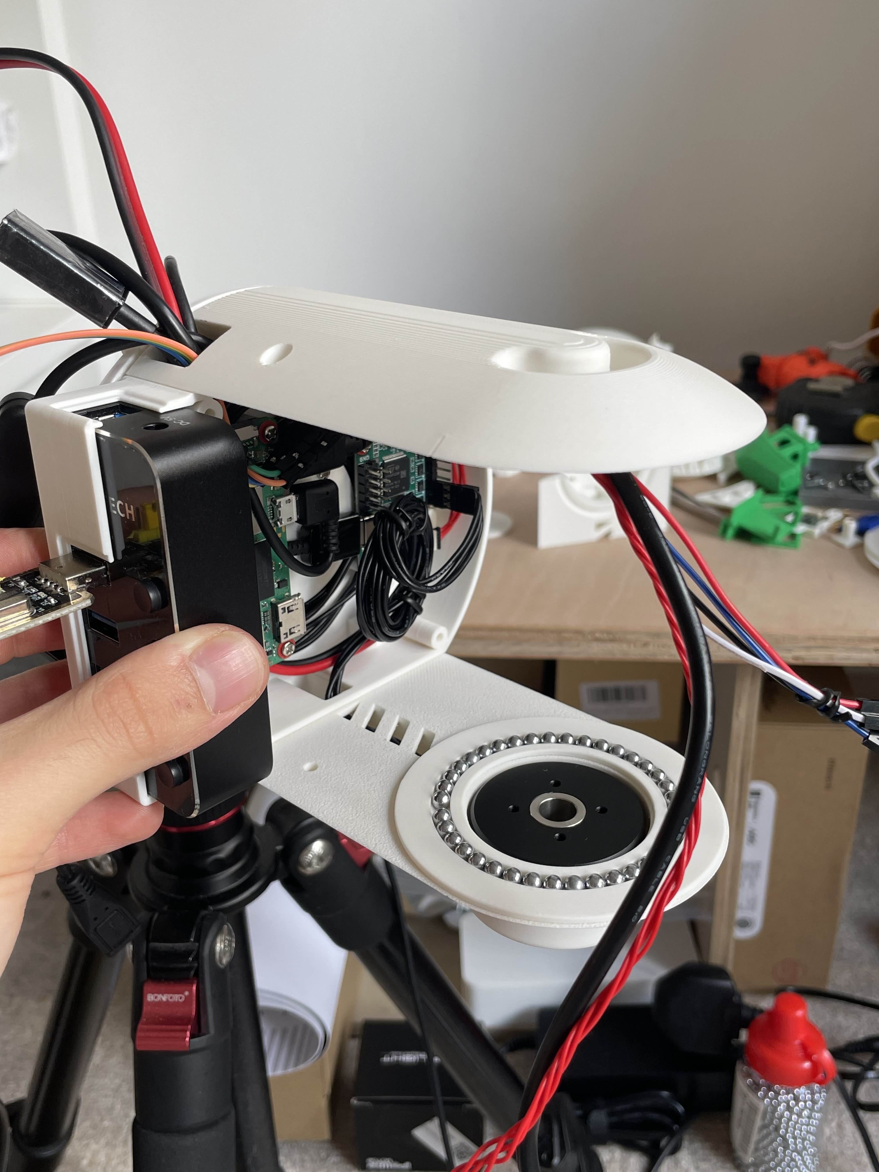
It was certainly not easy assembling it this far, as I ran into a few dimension, clearance, and access of fastener issues. I plan on correcting some of these oversights and issues in CAD once I've done some testing. Below is a list of some notable ones:
- R-BGM Arm cable route too small to fit USB-A headers
- R-BGM Arm cable route support removal was difficult
- USB-A cable headers didn't fit well into the system: Bulky and cable insulation is too thick & rigid
- X-Axis (vert) ball bearing interfaces made it difficult to assemble the payload (had to do it horizontally)
- Zero clearance between payload sphere (convex) and base top sphere (concave)
- Plastic holes didn't thread well with screws - unlike with threaded inserts
- Accessing payload inner comps and interfaces (IMU, L-side cover to BGM holes) is nearly impossible with both halves assembled
The next steps are to wire up the internal components (Ras Pi, BGMs, LRF, Mic array) and begin testing the gimbal motor control system and sensor data acquisition. I'll be posting more updates in the coming weeks as I progress further with Capstone's build and testing.
Fun times!
24 October, 2025
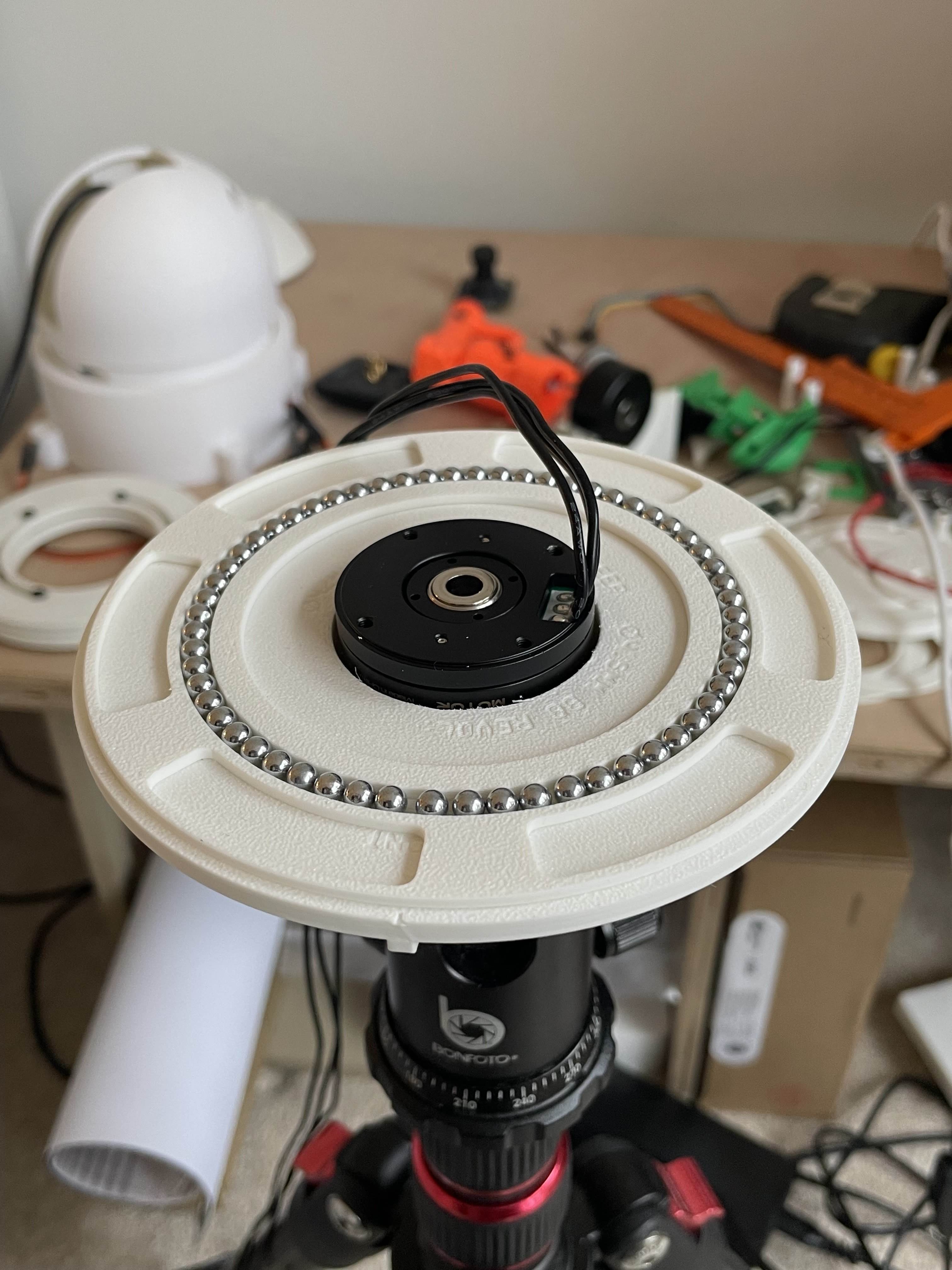
GIMBAL MOTOR, MOUNT, AND LRF TESTING

I have now got the laser rangefinder working and I have done some testing. The TXD and RXD data channels were swapped but the issue is now fixed and in my testing program, I was able to reduce the latency of distance readings to the Pi from ~52s to ~2s (a huge improvement). The unused readings were clogging up the RAM and CPU processing power of the Pi, so purging the old readings rapidly after new ones have come in (50-60 per second) improved the latency at which I could see the readings from the Pi program's output and made the whole sensor process pretty lightweight.
So more to come in the next two weeks, as I'll begin testing my planned mappings of the payload internal components (camera and LRF - Mic array is already done) and fixing wiring issues as currently some cable headers are too bulky to fit into such a tight space in the base compute housing (Ras Pi, Y axis BGM, Storm32 BGC) - I've eye-ed out some cables on AliExpress which may solve this problem.
I have also just received 2x A2 Slater Prints advertisement vinyl posters which I designed and ordered last week. I plan on putting one up outside my local Co-Op, and I was thinking of putting the other in Henley-on-Thames' town centre (I'll speak with the Henley council first of course) to hopefully attract my first few customers.
8 October, 2025
CAD PROGRESS, TESTING, AND 'SLATER PRINTS'
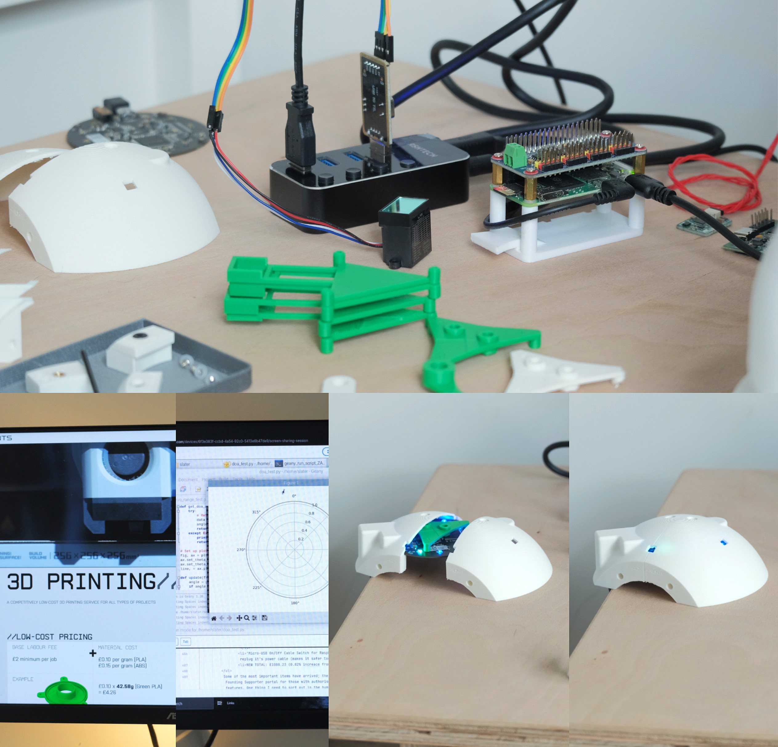
I have begun testing two of the primary sensors; the 4-mic array (acoustic drone detection & 2D location - NESW), and the laser range finder, which has given me some serial data connection issues, and I'm busy troubleshooting the issue to solve it (easily solvable). All testing has been done via my Raspberry Pi in the terminal & desktop (for GUI interpretation, like cardinal points display from the mic array). The gimbal motors have not arrived yet, but when they do I'll be testing those out with a rough shell of the Capstone system.
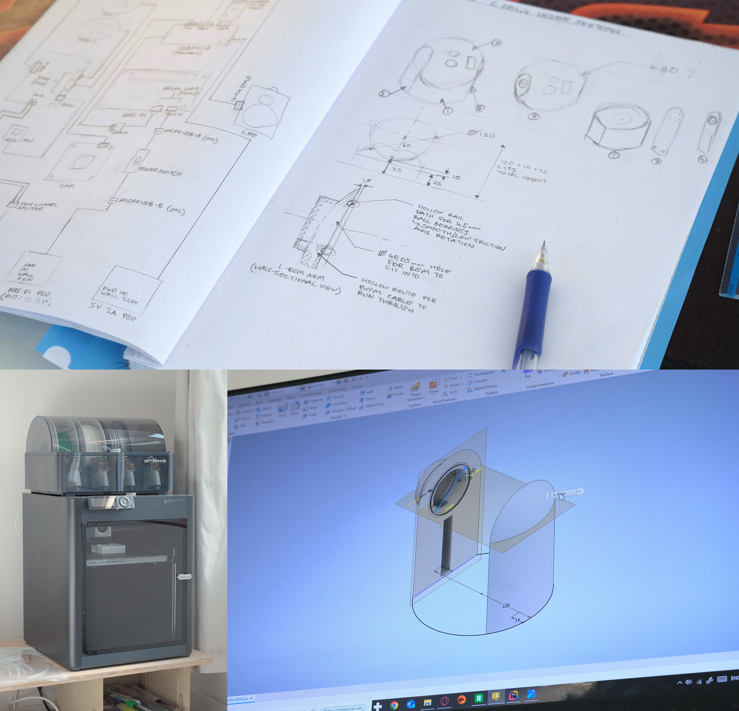
'Slater Prints' (Link: slaterindustries.uk/prints) is a sub-division of Slater Industries offering low-cost 3D printing services (using my Bambu Lab P1S) for additive manufacturing, custom parts, or home projects. I'm not going to allocate too much of my attention and effort to this portion of the business, but I'll rather use it as an attempt to bootstrap some profit to be used towards future funding for Slater Industries. I'll be distributing flyers and business cards to potential customers within my village in the coming days. I don't expect Slater Prints to get a lot of business - maybe a couple prints every month - but it's worth a shot, and as mentioned, I will be primarily focusing on Slater Industries, not Slater Prints.
24 September, 2025
ITEM DELIVERIES, DESIGN PROGRESS, AND NEXT STEPS
- 'Mini Laser Rangefinder Module, ODR-B' - Got a £4 discount on AliExpress
- '12V 5A 60W LED Power Supply' - Changed for a higher quality PSU
- 'Threaded Inserts for Plastic 308PCS' - Changed from 440pcs -> 308pcs to reduce postage ETA, also made it £2 cheaper
- 'Workdesk materials (Plywood, vanish)' - 1x Plywood sheet, 2x Wood boxes form B&Q. Price went from £30 -> £49 (£19 increase due to underestimation)
- 'NT IMU V4.2' - Changed quantity from 2 -> 1 for now (1 for testing, 2 later on). £21.66 decrease
- 'Bambu Lab PLA filament' - Got a 40% discount as part of printer purchase
- 'UART-TTL USB Adapter' - ADDITIONAL ITEM. Required for USB interface to RasPi from 4 individual cables from LRF
- 'Powered USB 3.0 Hub, 4-port, 5V/2A' - ADDITIONAL ITEM. Required to avoid overvoltage from RasPi's 5V source, used to power all external comps
- 'Micro-USB On/Off Cable Switch for Raspberry Pi' - ADDITIONAL ITEM. Nice to have as it allows me to power on the RasPi without having to unplug & replug it's power cable (makes it safer too)
- NEW TOTAL: £1088.23 (0.82% increace from £1079.42)
I've been designing C_001v4 in AutoDesk Inventor Professional on my desktop PC (which is well spec-ed) and I'll be testing fastener, ball bearing fittings, and part interfaces first once I've got a high level aof accuracy in my dimensions. The design in coming along good, so far I'm working on the Y-axis BGM (brushless gimbal motor) and main dome mount/arm.
I've also been chasing leads to schedule meetings which will allow me to learn more about painpoints and defence tech gaps on the battlefield with a focus on Ukraine-Russia conflict experts and Taiwanese naval experts, and I plan to get in contact with prison officers too to learn what civil/governmental needs for C-UAS or other dual-use tech exist and gaps Slater Industries could fill. If you have any connections iro the above, do get in contact with me via the contact page.
15 September, 2025
IT'S A GO!
Great things to come!